Six-Axis Robot Arm
A six-axis arm built from scratch, around cycloidal gearboxes I designed myself.
Role Solo project
Drag to turn · click a joint to look closer
The three driven joints
Each one got the reduction it needed
Each reducer housing is also the link it turns, so there is nothing here to take apart: the gearbox is the arm.
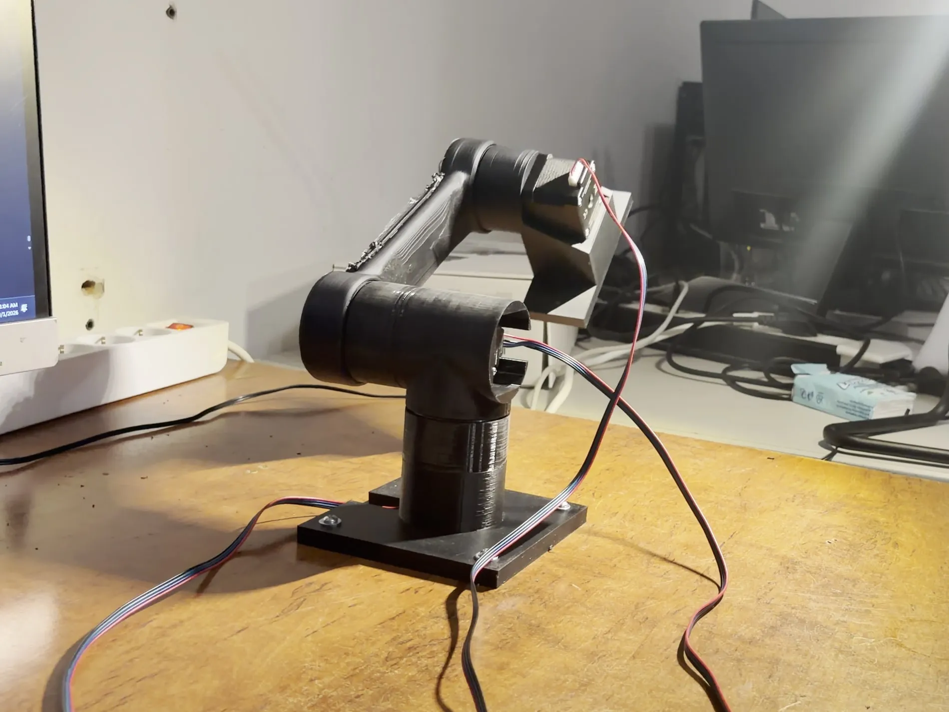
Six axes. The first three are steppers driving printed cycloidal reducers I designed, at 15:1, 20:1 and 15:1. The last three are servos. The gearboxes are not bolted on, they are the arm, each housing is a link and its output carries the next one. Three axes are built and moving.
What it is
Six axes. The first three carry the load and are steppers turning printed cycloidal reducers I designed, at 15:1, 20:1 and 15:1. The last three are the wrist, and those are servos.
The reducers are not parts bolted onto an arm. Each gearbox housing is a link, and its output plate carries the next one, so the structure and the transmission are the same object.
What I actually did
Designed the gearbox. The cycloidal disc profile, the eccentric, the bearing fits, the tolerances that survive a printer. Then designed the arm around it, drew the driver board, and wrote the firmware that moves it.
It runs smoothly and there is very little backlash in it, which for a printed reducer is the whole question.
Where it is now
Three axes are built and moving, in the clip above. Firmware takes joint angles over serial, converts them to steps, and drives the motors, with a pile of debug commands behind it for jogging, homing and limits. No inverse kinematics yet.
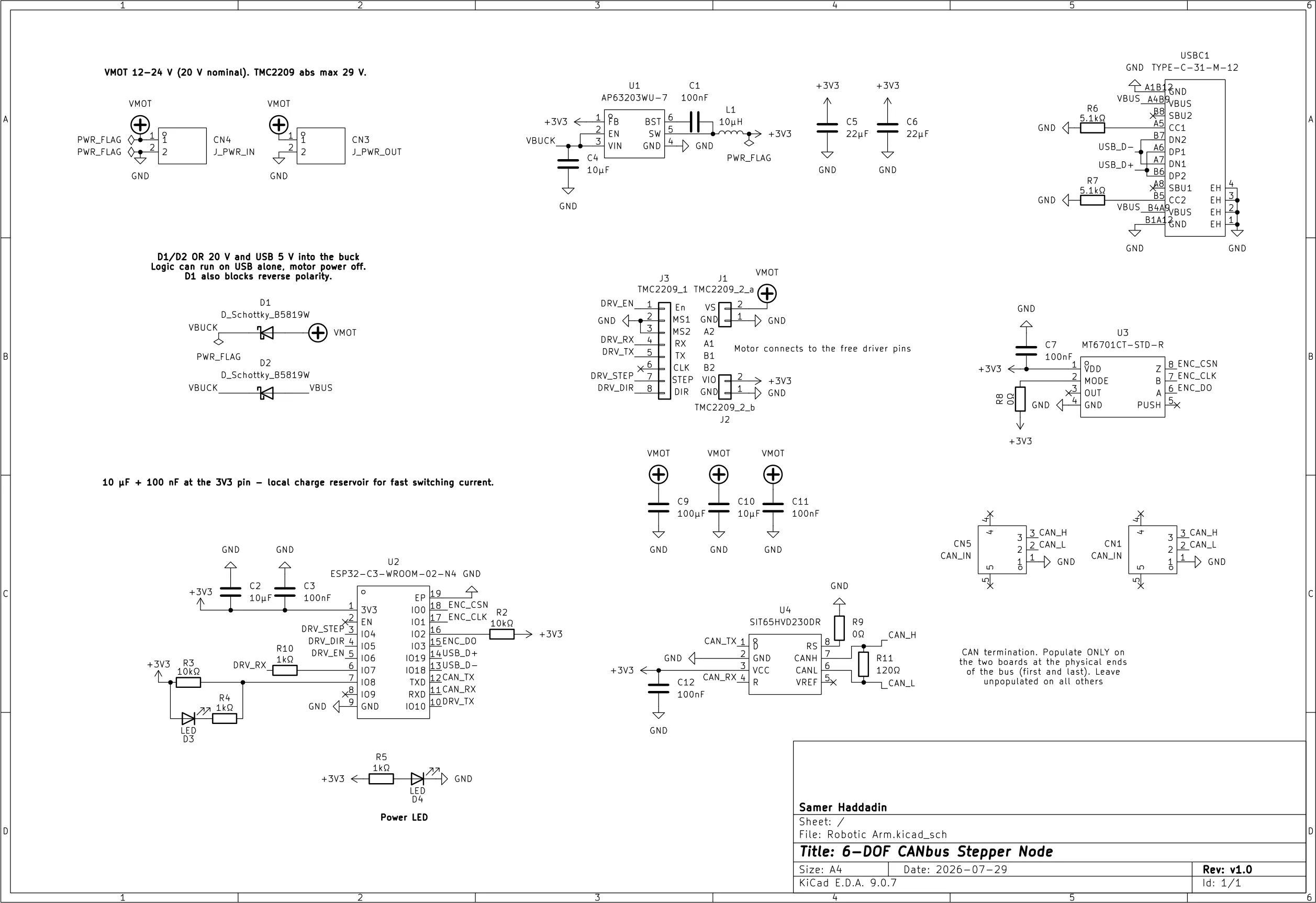
The driver board is drawn: an ESP32-C3, a socketed TMC2209, an MT6701 encoder and a CAN transceiver, one board per joint, all six on one bus.
The plan, in order
- Finish all six axes. Get the arm complete and moving before making any part of it clever.
- Then close the loop on the first three. That is what the encoder and the per-joint board are for. The wrist servos are closed loop already, so only the stepper joints need it.
Signal path
05 stages- 01 Angles one per joint
- 02 Firmware step + direction
- 03 TMC2209 one per stepper
- 04 NEMA 17 through the reducer
- 05 Joint 15:1, 20:1, 15:1
No inverse kinematics yet. You give it joint angles and it goes there, which was enough to get three axes moving and to find out what the mechanics actually do.
On paper
01 sheetSheet 1/1 · Rev v1.0
On video
01 clipsMore
01 photos